Archive
Dysfunctional Interactions
In “Engineering A Safer World“, Nancy Leveson states that dysfunctional interactions between system parts play a bigger role in accidents than individual part failures. Relative to yesterday’s systems, today’s systems contain many more parts. But because of manufacturing advances, each part is much more reliable than it used to be.
A consequence of adding more parts to a system is that the numbers of potential connections and interactions between parts starts exploding fast. Hence, there’s a greater chance of one dysfunctional interaction crashing the whole system – even whilst the individual parts and communication links continue to operate reliably.

Even with a “simple” two part system, if its designed-in purpose requires many rich and interdependent interactions to be performed over the single interface, watch out. A single dysfunctional interaction can cause the system to seize up and stop producing the emergent behavior it was designed to provide:

So, what’s the lesson here for system designers? It’s two-fold. Minimize the number of interfaces in your design and, more importantly, limit the number, types, and exchanges over each interface to only those that are required to fulfill the system’s purpose. Of course, if no one knows what’s required (which is the number one cause of unsuccessful systems), then you’re hosed no matter what. D’oh!
A Bunch Of STIFs
In “Object-Oriented Analysis and Design with Applications“, Grady Booch argues that a successful software architecture is layered, object-oriented, and evolves over time as a series of STIFs – STable Intermediate Forms. The smart and well liked BD00 agrees; and he adds that unsuccessful architectures devolve over time as a series of unacknowledged UBOMs (pronounced as “You Bombs“).

UBOMs are subtle creatures that, without caring stewardship, can unknowingly sneak up on you. Your first release or two may start out as a successful STIF or a small and unobtrusive UBOM. But then, since you’ve stepped into UBOM-land, it can grow into an unusable, resource-sucking abomination. Be careful, very careful….
“Who advocates for the product itself—its conceptual integrity, its efficiency, its economy, its robustness? Often, no one.” – Fred Brooks
“Dear Fred, when the primary thought held steadfast in everybody’s mind is “schedule is king” instead of “product is king“, of course no one will often advocate for the product.” – BD00
Unavailable For Business
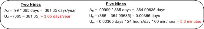
The availability of a system is usually specified in terms of the “number of nines” it provides. For example, a system with an availability specification of 99.99 provides “two nines” of availability. As the figure below shows, a service that is required to provide five nines of availability can only be unavailable 5.3 minutes per year!

Like most of the “ilities” attributes, the availability of any non-trivial system composed of thousands of different hardware and software components is notoriously difficult and expensive to predict or verify before the system is placed into operation. Thus, systems are deployed and fingers crossed in the hope that the availability it provides meets the specification. D’oh!
One way of supposedly increasing the availability of a system is to add redundancy to its design (see the figure below). But redundancy adds more complex parts and behavior to an already complex system. The hope is that the increase in the system’s unavailability and cost and development time caused by the addition of redundant components is offset by the overall availability of the system. Redundancy is expensive.

As you might surmise, the switch in the redundant system above must be “smart“. During operation, it must continuously monitor the health of both output channels and automatically switch outputs when it detects a failure in the currently active channel.
The state transition diagram below models the behavior required of the smart switch. When a switchover occurs due to a detected failure in the active channel, the system may become temporarily unavailable unless the redundant subsystem is operating as a hot standby (vs. cold standby where output is unavailable until it’s booted up from scratch). But operating the redundant channel as a hot standby stresses its parts and decreases overall system availability compared to the cold spare approach. D’oh!

Another big issue with adding redundancy to increase system availability is, of course, the BBoM software. If the BBoM running in the redundant channel is an exact copy of the active channel’s software and the failure is due to a software design or implementation defect (divide by zero, rogue memory reference, logical error, etc), that defect is present in both channels. Thus, when the switch dutifully does its job and switches over to the backup channel, it’s output may be hosed too. Double D’oh! To ameliorate the problem, a “software 2” component can be developed by an independent team to decrease the probability that the same defect is inserted at the same place. Talk about expensive?
Achieving availability goals is both expensive and difficult. As systems become more complex and human dependence on their services increases, designing, testing, and delivering highly available systems is becoming more and more important. As the demand for high availability continues to ooze into mainstream applications, those orgs that have a proven track record and deep expertise in delivering highly available systems will own a huge competitive advantage over those that don’t.
Benevolent Dictators And Unapologetic Aristocrats
The Editor in Chief of Dr. Dobb’s Journal, Andrew Binstock, laments about the “committee-ization” of programming languages like C, C++, and Java in “In Praise of Benevolent Language Dictators“:
Where the vision (of the language) is maintained by a single individual, quality thrives. Where committees determine features, quality declines inexorably: Each new release saps vitality from the language even as it appears to remedy past faults or provide new, awaited capabilities.
I think Andrew’s premise applies not only to languages, but it also applies to software designs, architectures, and even organizations of people. These constructs are all “systems” of dynamically interacting elements wired together in order to realize some purpose – not just bags of independent parts. As an example, Fred Brooks, in his classic book, “The Mythical Man-Month“, states:
To achieve conceptual integrity, a design must proceed from one mind or a small group of agreeing minds.
If a system is to have conceptual integrity, someone must control the concepts. That is an aristocracy that needs no apology.
The greater the number of people involved in a concerted effort, the lower the coherency within, and the lower the consistency across, the results. That is, unless a benevolent dictator or unapologetic aristocrat is involved AND he/she is allowed to do what he/she decides must be done to ensure that conceptual integrity is preserved for the long haul.
Of course, because of the relentless increase in entropy guaranteed by the second law of thermodynamics, all conceptually integrated “closed systems” eventually morph into a disordered and random mess of unrelated parts. It’s just a matter of when, but if an unapologetic aristocrat who is keeping the conceptual integrity of a system intact leaves or is handcuffed by clueless dolts who have power over him/her, the system’s ultimate demise is greatly accelerated.

DataLoggerThread
The figure below models a program in which a pipeline of worker threads communicate with each other via message passing. The accordion thingies ‘tween the threads are message queues that keep the threads loosely coupled and prevent message bursts from overwhelming downstream threads.

During the process of writing one of these multi-threaded programs to handle bursty, high rate, message streams, I needed a way to periodically extract state information from each thread so that I could “see” and evaluate what the hell was happening inside the system during runtime. Thus, I wrote a generic “Data Logger” thread and added periodic state reporting functionality to each worker thread to round out the system:

Because the reporting frequency is low (it’s configurable for each worker thread and the default value is once every 5 seconds) and the state report messages are small, I didn’t feel the need to provide a queue per worker thread – YAGNI.
The figure below shows a more detailed design model of the data logging facility in the form of a “bent” UML class diagram. Upon construction, each DataLoggerThread object can be configured to output state messages to a user named disk file and/or the global console during runtime. The rate at which a DataLoggerThread object “pops” state report messages from its input queue is also configurable.

The DataLoggerThread class provides two different methods of access to user code at runtime:
void DataLoggerThread::record_txt_block(const Data&)
and
void DataLoggerThread::operator<<(const Data&).
Objects of the DataLoggerThread class run in their own thread of execution – transparently in the background to mainline user code. On construction, each object instance creates a mutex-protected, inter-thread queue and auto-starts its own thread of operation behind the scenes. On destruction, the object gracefully self-terminates. During runtime, each DataLoggerThread object polls its input queue and formats/writes the queue entries to the global console (which is protected from simultaneous, multiple thread access by a previously developed CoutMonitor class) and/or to a user-named disk log file. The queue is drained of all entries on each (configurable,) periodic activation by the underlying (Boost) threads library.
DataLoggerThread objects pre-pend a “milliseconds since midnight” timestamp to each log entry just prior to being pushed onto the queue and a date-time stamp is pre-pended to each user supplied filespec so that file access collisions don’t occur between multiple instances of the class.
That’s all I’m gonna disclose for now, but that’s OK because every programmer who writes soft, real-time, multi-threaded code has their own homegrown contraption, no?
“As-Built” Vs “Build-To”
The figure below shows one (way too common) approach for developing computer programs. From an “understanding” in your head, you just dive into the coding state and stay there until the program is “done“. When it finally is “done“: 1) you load the code into a reverse engineering tool, 2) press a button, and voila, 3) your program “As-Built” documentation is generated.

For trivial programs where you can hold the entire design in your head, this technique can be efficient and it can work quite well. However, for non-trivial programs, it can easily lead to unmaintainable BBoMs. The problem is that the design is “buried” in the code until after the fact – when it is finally exposed for scrutiny via the auto-generated “as-built” documentation.
With a dumb-ass reverse engineering tool that doesn’t “understand” context or what the pain points in a design are, the auto-generated documentation is often overly detailed, unintelligible, camouflage in which a reviewer/maintainer can’t see the forest for the trees. But hey, you can happily tick off the documentation item on your process checklist.
Two alternative, paygo types of development approaches are shown below. During development, the “build-to” design documentation and the code are cohesively produced manually. Only the important design constructs are recorded so that they aren’t buried in a mass of detail and they can be scrutinized/reviewed/error-corrected in real-time during development – not just after the fact.

I find that I learn more from the act of doing the documentation than from pushing an “auto-generate” button after the fact. During the effort, the documentation often speaks to me – “there’s something wrong with the design here, fix me“.
Design is an intimate act of communication between the creator and the created – Unknown
Of course, for developers, especially one dimensional extreme agilista types who have no desire to “do documentation” or learn UML, the emergence of reverse engineering tools has been a Godsend. Bummer for the programmer, the org he/she works for, the customer, and the code.
Distributed Functions, Objects, And Data
During a discussion on LinkedIn.com, the following distributed system communication architectural “styles” came up:
- DF == Distributed Functions
- DO == Distributed Objects
- DD == Distributed Data
I felt the need to draw a picture of them, so here it is:

The DF and DO styles are point-to-point, client-server oriented. Client functions invoke functions and object methods invoke object methods on remotely located servers.
The DD style is many-to-many, publisher-subscriber oriented. A publisher can be considered a sort of server and subscribers can be considered clients. The biggest difference is that instead of being client-triggered, communication is server-triggered in DD systems. When new data is available, it is published out onto the net for all subscribers to consume. The components in a DD system are more loosely coupled than those in DF and DO systems in that publishers don’t need to know anything (no handles or method signatures) about subscribers or vice versa – data is king. Nevertheless, there are applications where each of the three types excel over the other two.
Complicated != Complex
For the non-geeks reading this post, the “!=” symbol is the C++ programming language token for “not equal“.
It seems like a lot of people think that classifying something as “complex” is the same as calling it “complicated“, and vice-versa. That conclusion can be, and often is, true, but it can also be false. I associate “complicated” with “not-understandable” – except to a select few experts. I think of “complex” to be the equivalent of something like “intricately elegant” and understandable to far more people than just experts.
Let’s take an example to illuminate my viewpoint. Assume that the black box system below functions delightfully. It’s reliable, responsive, easy to learn, and does what its users want without frustrating them in the slightest.
 Now, in terms of complicated and complex, consider what the system may look like under the covers:

Of course, most users don’t give a shite what goes on under the covers, but the designing org and its people better well know what does – unless they luckily don’t have any competition to deal with, and hence, have their customers in a vice grip.
You see, at some point in time, the users will want improvements to the system as their needs evolve. If the original team of builders of implementation #1 are the only people who know the (so-called) design well enough to change it without breaking any existing capabilities, then the development org is hosed if those people leave. In effect, the org is held hostage by a small cadre of people. D’oh!
In the complex-complex implementation on the far right, even if the original builders leave the development org, the (relatively) elegant and well thought out design structure facilitates easy on-boarding of replacement builders. As an added bonus, the effort needed to add features and enhancements to the product is way less costly and risky than the other jaggedly complicated implementations.
So, given the portfolio of products in your org, how would you assess them in terms of the complexity and complicated attributes? If, and it’s probably a big IF, you could publicly communicate your assessment without fear of marginalization, or worse, how many people in your org do you think would publicly agree with your assessment? Uh, how abut privately? Would the number of public “agreers” match the number of private “agreers“?

Pegged
Peg, It will come back to you – Steely Dan
Assume that as a sub-task of redesigning a BBoM chunk of legacy software for scalability (single thread to mutliple threads), you have to “do something” with a subset of high performance, but computationally dense and tricky, C procedural code. Let’s call the functionality implemented by this code “peg“.
In the figure below, I model the procedural mess that is “peg” on the left as an M function call tree in which many of the functions perform CRUD accesses on a set of K interrelated global data structures. Trust me when I say that K and M are non-trivial, double digit numbers. D’oh!

The way I see it, I have three choices for attacking the monolith:

Options 1 and 2 are slightly different instances of the ultra-conservative “sarcophagus” pattern (remember Chernobyl?). Option 3, which is technically riskier, higher latency, and higher development cost in the short term, will definitely pay off in terms of lower maintenance costs and lower developer anxiety the long term – if done correctly!
If it was my decision alone (and it should be since I’ll be doing all the coding/testing/documenting/defending/”owning“, no?), I’d choose option 3 without blinking an eye. I wouldn’t blink an eye because I know that “peg” will continue to need to be extended and enhanced for many years into the future – and maintenance costs far exceed initial developments costs in all software product life cycles. But alas, I’m just a dumb engineer with no business sense.
SysML, UML, MML
I really like the SysML and UML for modeling and reasoning about complex, multi-technology and software-centric systems respectively, but I think they have one glaring shortcoming. They aren’t very good at modeling distributed, multi-process, multi-threaded systems. Why? Because every major element (except for a use case?) is represented as a rectangle. As far as I know, a process can be modeled as either a parallelogram or a stereotyped rectangular UML class (SysML block ):

To better communicate an understanding of multi-threaded, multi-process systems, I’ve created my own graphical “proprietary” (a.k.a. homegrown) symbology. I call it the MML (UML profile). Here is the MML symbol set.

An example MML diagram of a design that I’m working on is shown below. The app-specific modeling element names have been given un-descriptive names like ATx, APx, DBx, Mx for obvious reasons.

Compare this model with the equivalent rectangular UML diagram below. I purposely didn’t use color and made sure it was bland so that you’d answer the following question the way I want you to. Which do you think is more expressive and makes for a better communication and reasoning tool?

If you said “the UML diagram is better“, that’s OK. 🙂
Who am I?
Why am I here?
WTF?
Meh!
D'oh!
My BTC Address

