Archive
Big Design, But Not All Upfront
When not ranting and raving on this blawg about “great injustices” (LOL) that I perceive are keeping the world from becoming a better place, I design, write, and test real-time radar system software for a living. I use the UML before, during, and after coding to capture, expose, and reason about my software designs. The UML artifacts I concoct serve as a high level coding road map for me; and a communication tool for subject matter experts (in my case, radar system engineers) who don’t know how to (or care to) read C++ code but are keenly interested in how I map their domain-specific requirements/designs into an implementable software design.
I’m not a UML language lawyer and I never intend to be one. Luckily, I’m not forced to use a formal UML-centric tool to generate/evolve my “bent” UML designs (see what I mean by “bent” UML here: Bend It Like Fowler). I simply use MSFT Visio to freely splat symbols and connections on an e-canvas in any way I see fit. Thus, I’m unencumbered by a nanny tool telling me I’m syntactically/semantically “wrong!” and rudely interrupting my thought flow every five minutes.
The 2nd graphic below illustrates an example of one of my typical class diagrams. It models a small, logically cohesive cluster of cooperating classes that represent the “transmit timeline” functionality embedded within a larger “scheduler” component. The scheduler component itself is embedded within yet another, larger scale component composed of a complex amalgam of cooperating hardware and software components; the radar itself.
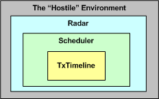
When fully developed and tested, the radar will be fielded within a hostile environment where it will (hopefully) perform its noble mission of detecting and tracking aircraft in the midst of random noise, unwanted clutter reflections, cleverly uncooperative “enemy” pilots, and atmospheric attenuation/distortion. But I digress, so let me get back to the original intent of this post, which I think has something to do with how and why I use the UML.
The radar transmit timeline is where other necessarily closely coupled scheduler sub-components add/insert commands that tell the radar hardware what to do and when to do it; sometime in the future relative to “now“. As the radar rotates and fires its sophisticated, radio frequency pulse trains out into the ether looking for targets, the scheduler is always “thinking” a few steps ahead of where the antenna beam is currently pointing. The scheduler relentlessly fills the TxTimeline in real time with beam-specific commands. It issues those commands to the hardware early enough for the hardware to be able to queue, setup, and execute the minute transmit details when the antenna arrives at the desired command point. Geeze! I’m digressing yet again off the UML path, so lemme try once more to get back to what I originally wanted to ramble about.
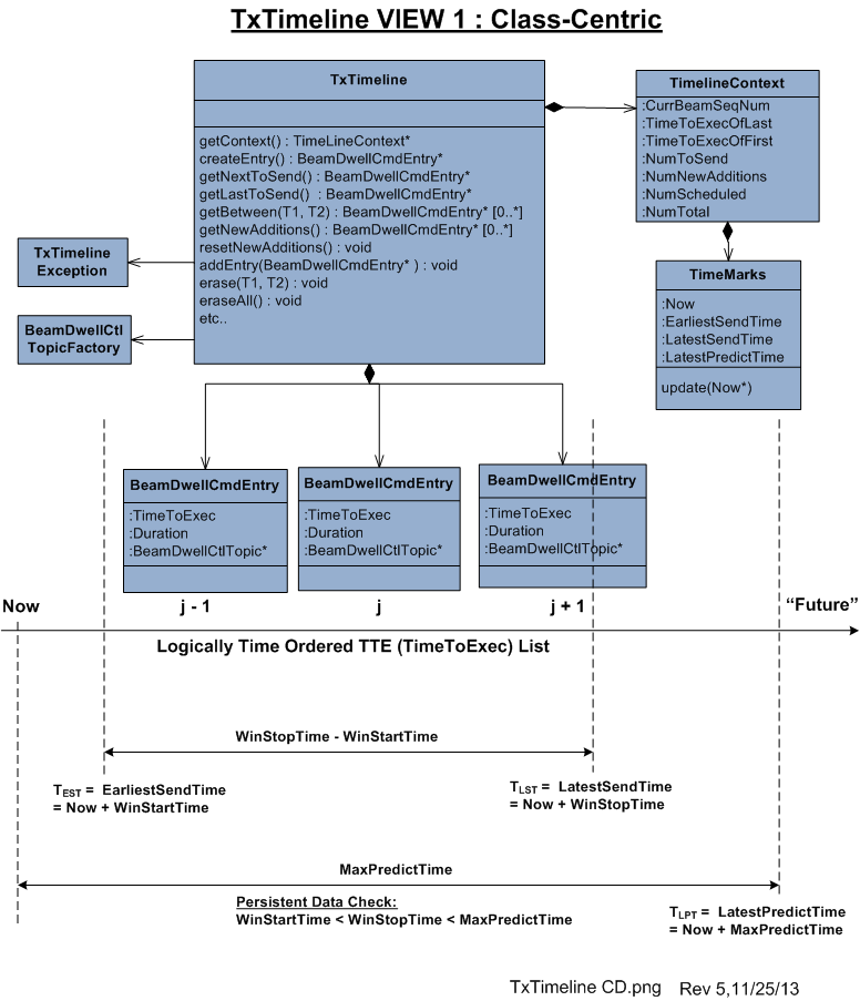
Being an unapologetic UML bender, and not a fan of analysis-paralysis, I never attempt to meticulously show every class attribute, operation, or association on a design diagram. I weave in non-UML symbology as I see fit and I show only those elements I deem important for creating a shared understanding between myself and other interested parties. After all, some low level attributes/operations/classes/associations will “go away” as my learning unfolds and others will “emerge” during coding anyway, so why waste the time?
Notice the “revision number” in the lower right hand corner of the above class diagram. It hints that I continuously keep the diagram in sync with the code as I write it. In fact, I keep the applicable diagram(s) open right next to my code editor as I hack away. As a PAYGO practitioner, I bounce back and forth between code & UML artifacts whenever I want to.
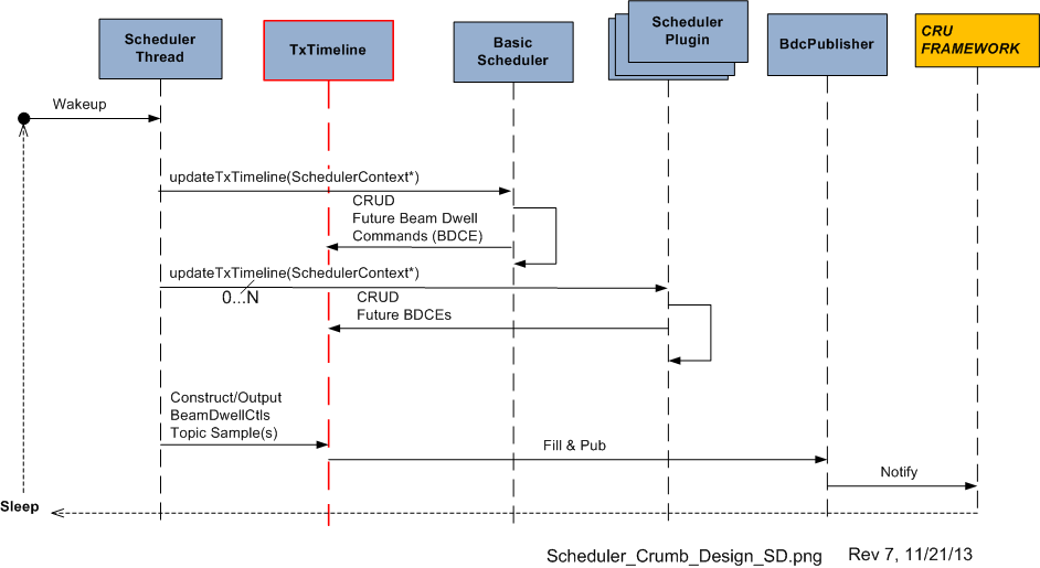
The UML sequence diagram below depicts a visualization of the participatory role of the TxTimeline object in a larger system context comprised of other peer objects within the scheduler. For fear of unethically disclosing intellectual property, I’m not gonna walk through a textual explanation of the operational behavior of the scheduler component as “a whole“. The purpose of presenting the sequence diagram is simply to show you a real case example that “one diagram is not enough” for me to capture the design of any software component containing a substantial amount of “essential complexity“. As a matter of fact, at this current moment in time, I have generated a set of 7+ leveled and balanced class/sequence/activity diagrams to steer my coding effort. I always start coding/testing with class skeletons and I iteratively add muscles/tendons/ligaments/organs to the Frankensteinian beast over time.
In this post, I opened up my trench coat and showed you my… attempted to share with you an intimate glimpse into the way I personally design & develop software. In my process, the design is not done “all upfront“, but a purely subjective mix of mostly high and low level details is indeed created upfront. I think of it as “Big Design, But Not All Upfront“.
Despite what some code-centric, design-agnostic, software development processes advocate, in my mind, it’s not just about the code. The code is simply the lowest level, most concrete, model of the solution. The practices of design generation/capture and code slinging/testing in my world are intimately and inextricably coupled. I’m not smart enough to go directly to code from a user story, a one-liner work backlog entry, a whiteboard doodle, or a set of casual, undocumented, face-to-face conversations. In my domain, real-time surveillance radar systems, expressing and capturing a fair amount of formal detail is (rightly) required up front. So, screw you to any and all NoUML, no-documentation, jihadists who happen to stumble upon this post. 🙂
Monopolistic Providers
In search of economies of scale, centrally planned and controlled economies in nations and corporations tend to create monopolistic providers of goods and services. For example, in corporations, accounting, personnel, and R&D departments are usually deliberately organized as subsidized monopolies. They are subsidized in the sense that the users of their products or services do not pay for them directly; the supplying units are supported financially by funds that are allocated to them from above. The pool from which these funds are drawn is filled by a “tax” allocated from above to the units served. Monopolistic units that are subsidized are generally insensitive and unresponsive to the users of their services, but they are sensitive and responsive to the desires of the higher-level units that subsidize them. These higher level units are even more removed from the units served than the serving units. As a result, they are often unaware of, or unresponsive to, the needs and desires of the internal users of monopolistically provided goods and services. – Russell Ackoff (Ackoff’s Best: His Classic Writings on Management)
OK, time to practice my “bent” UML modeling skills and test your understanding with the class and sequence diagram pair below. The class diagram provides a structural view of a fictional Ackoffian system. The sequence diagram steps through an amalgam of behaviors in a world where monopolies rule. Any questions, comments, critiques, accolades, WTFs?


operateUntilDeath()
Putting aside the “NotYouAndMe” class name in the bogus BD00 model below for a moment, I think most powerful and wealthy people believe that they can willfully control their feelings, actions, and behaviors via a “Conscious Executive” entity hosted within their brain. Objects of this fictitious class “require” and are “provided” energy by the one and only “life force“.
“NotYouAndMe” objects continually execute the “operateUntilDeath()” function in a “while(alive)” loop until the “life force” asynchronously pulls the plug – which can be anytime and anywhere. D’oh!

Each cycle through the “operateUntilDeath()” function goes something like this:
- Poll your senses for objects and events “out there“.
- Evaluate the sensor input data against prior memories accumulated and stored in your “Experience Database“.
- Speak/act according to whether you consciously perceive the current landscape as a threat or an opportunity.
The only problem with the model above (beside the fact that it’s another whacky BD00 concoction) is the “conscious” part playing the CEO of your corpus. That’s why the aggregator class is aptly named “NotYouAndMe“. To see this fallacy more vividly, feast your eyes upon the real, Nobel prize winning “YouAndMe” model below.

The BD00 mandated reality is that there’s a hidden and oft-denied “Unconscious Executive” behind the scenes that enables/disables the “Conscious Executive” object whenever it damn well pleases. In effect, the “Conscious Executive” gets sloppy seconds on the sensor data only after it’s been censored and chewed up by the “Unconscious Executive”. In totally clueless people like BD00, the “Conscious Executive” is rarely, if ever, “enabled“. D’oh!
How about you dear reader? Do you believe that you’re “fully in control and in charge”? Are you a “Conscious Executive“? The more you believe it, the less it is.
Spiritual UML
Because he is the chosen one, the universe spaketh to BD00 last night: “Go forth my son, and employ the UML to teach the masses the true nature of the mind!“. Fearful of being annihilated if he didn’t comply, BD00 sat down and waited for an infusion of cosmic power to infiltrate his being (to catalyze the process, BD00 primed the pump with a three olive dirty ‘tini and hoped the universe didn’t notice).
With mouse in trembling hand and an empty Visio canvas in front of him, BD00 waited…. and waited… and waited. Then suddenly, in mysterious Ouja board fashion, the mouse started moving and clicking away. Click, click, click, click.
After exactly 666 seconds, “revision 0” was 90% done. The secrets of the metaphysical that have eluded the best and brightest over the ages were captured and revealed in the realm of the physical! Lo and behold….. the ultimate UML class diagram:

Of course, the “Thought Factory” class is located in China. It efficiently and continuously creates (at rock bottom labor costs) every thought that comes/stays/goes through each of the 7 billion living brains on earth.
Design Disclosure
Recently, I had to publicly disclose the design of the multi-threaded CSCI (Computer Software Configuration Item) that I’m currently bringing to life with a small group of colleagues. The figure below shows the entities (packages, CSCs (Computer Software Components), Classes) and the inter-entity relationship schema that I used to create the CSCI design artifacts.

As the figure illustrates, the emerging CSCI contains M packages and K top level CSCs . Each package contains from 1 to N 2nd level CSCs that associate with each other via the “communicates” (via messages) relationship. Each CSC is of the “passive” or “active” class type, where “active” means that the CSC executes within its own thread of control.
Using the schema, I presented the structural and behavioral aspects of the design as a set of views:
- The threads view (behavioral )
- The packages view (structural)
- The class diagrams view (structural)
- The sequence diagrams view (behavioral)
Like any “real” design effort (and unlike the standard sequential design-code-test mindset of “authorities“), I covertly used the incremental and iterative PAYGO methodology (design-a-little, code-a-little, test-a-little, document-a-little) in various mini sequences that, shhhh – don’t tell any rational thinker, just “felt right” in the moment.

As we speak, the effort is still underway and, of course, the software is 90% done. Whoo Hoo! Only 10 more percent to go.
Manager Types II
This post is an updated refinement of BD00’s class hierarchy for the manager types previously presented in the UCBH post. For your viewing displeasure, I’ve reproduced the “rev 0” version of the inheritance tree here:

The “rev 1” version, with all class operations elided because they’re not important for understanding the message I want to get across, is shown below. The absence of the “Tweener” in rev 0, which inherits the attributes and operations from both the “Bozo” and “Helper” classes, was a major mistake.

“Rev 1” is a much more accurate mental model of the manager kingdom because, as the probability density function below shows, the vast majority of manager “objects” are of the relatively boring, harmless, and ho-hum “Tweener” type.

If you look closely at the threshold locations in the scraggly drawn probability distribution, BD00 has postulated that even though the population is comprised mostly of “Tweeners“, there are more BMs than PHORs. Do you agree?
Luckily and happily, BD00 has never worked for, or with, a conscious BM. But he’s directly heard, and indirectly read, several stories from those poor souls who have (are you one of them?). Thus, BD00 is convinced that they do exist in nature.
All models are wrong. Some, however, are useful – George Box
SysML, UML, MML
I really like the SysML and UML for modeling and reasoning about complex, multi-technology and software-centric systems respectively, but I think they have one glaring shortcoming. They aren’t very good at modeling distributed, multi-process, multi-threaded systems. Why? Because every major element (except for a use case?) is represented as a rectangle. As far as I know, a process can be modeled as either a parallelogram or a stereotyped rectangular UML class (SysML block ):

To better communicate an understanding of multi-threaded, multi-process systems, I’ve created my own graphical “proprietary” (a.k.a. homegrown) symbology. I call it the MML (UML profile). Here is the MML symbol set.

An example MML diagram of a design that I’m working on is shown below. The app-specific modeling element names have been given un-descriptive names like ATx, APx, DBx, Mx for obvious reasons.

Compare this model with the equivalent rectangular UML diagram below. I purposely didn’t use color and made sure it was bland so that you’d answer the following question the way I want you to. Which do you think is more expressive and makes for a better communication and reasoning tool?

If you said “the UML diagram is better“, that’s OK. 🙂
void Manager::pitchInWhereNeeded(const Work& w){}
Unless you’re a C++ programmer, you probably won’t understand the title of this post. It’s the definition of the “pitchInWhereNeeded” member function of a “Manager” class. If you look around your immediate vicinity with open eyes, that member function is most likely missing from your Manager class definition. If you’re a programmer, oops, I mean a software engineer, it’s probably also missing from your derived “SoftwareLead“, “SoftwareProjectManager“, and “SoftwareArchitect” classes too.
As the UML-annotated figure below shows, in the early twentieth century the “pitchInWhereNeeded” function was present and publicly accessible by other org objects. On revision number 1 of the “system”, as signaled by the change from “+” to “-“, its access type was changed to private. This seemingly minor change broke all existing “system” code and required all former users of the class to redesign and retest their code. D’oh!

On the second revision of the Manager class, this critical, system-trust-building member function mysteriously disappeared completely. WTF?. This rev 2 version of the code didn’t break the system, but the system’s responsiveness decreased since private self -calls by manager objects to the “pitchInWhereNeeded” function were deleted and more work was pushed back into the “other” system objects. Bummer.

whatIsThisFor
Check out this C++ code fragment at the beginning of the MessageBase class template definition:

After staring at it for a few minutes, I was able to distill the essence of the idiom(???) used in the code as:

I can’t figure out why B was designed as a class template and not just a plain ole’ class that simply inherits from A (see below). It reminds me a little of the CRTP idiom but it’s not the same. Would you happen to know what problems it is intended to solve? Is it some template meta-programming technique?

XML In UML
While learning XML, I concocted this UML class diagram of the conceptual structure of XML as a quick look refresher guide:

The diagram can be interpreted as:
- A typical XML document is composed of a “Document Element“, an optional “Prolog Element”, and many application specific “Element” classes.
- Besides a base “Element” class, there are two subclass types: the “Document Element” and the “Prolog Element”.
- In an XML file, the “Prolog Element” (if present) must precede the “Document Element”.
- An element contains content and, optionally, 1 or more “Attributes”.
- Each “Attribute” is comprised of a Name/Value pair.
- An element can also contain other nested elements, providing support for structured data representation.
Here’s a simple concrete example XML file and the mapping from concrete to abstract. Note that the “comment” and “xml declaration” lines aren’t represented in the abstract class diagram model. I left out that second order level of detail to keep the class diagram simple.

Who am I?
Why am I here?
WTF?
Meh!
D'oh!
My BTC Address