Archive
The Meta-Documentation Dilemma
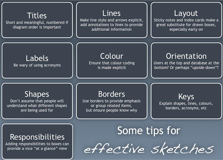
In his terrific “Effective architecture sketches” slide deck, Simon Brown rightly states that you don’t need UML to sketch up your software architecture. However, if you don’t, you need to consider documenting the documentation:
The utility of using a standard like UML is that you don’t have to spend any time on all the arcane subtleties of meta-documentation. And if you’re choosing to bypass the UML, you’re probably not going to spend much time, if any, doing meta-documentation to clarify your architecture decisions. After all, doing less documentation, let alone writing documentation about the documentation, is why you eschewed UML in the first place.
So, good luck in unambiguously communicating the software architecture to your stakeholders; especially those poor souls who will be trying to build the beast with you.
Big Design, But Not All Upfront
When not ranting and raving on this blawg about “great injustices” (LOL) that I perceive are keeping the world from becoming a better place, I design, write, and test real-time radar system software for a living. I use the UML before, during, and after coding to capture, expose, and reason about my software designs. The UML artifacts I concoct serve as a high level coding road map for me; and a communication tool for subject matter experts (in my case, radar system engineers) who don’t know how to (or care to) read C++ code but are keenly interested in how I map their domain-specific requirements/designs into an implementable software design.
I’m not a UML language lawyer and I never intend to be one. Luckily, I’m not forced to use a formal UML-centric tool to generate/evolve my “bent” UML designs (see what I mean by “bent” UML here: Bend It Like Fowler). I simply use MSFT Visio to freely splat symbols and connections on an e-canvas in any way I see fit. Thus, I’m unencumbered by a nanny tool telling me I’m syntactically/semantically “wrong!” and rudely interrupting my thought flow every five minutes.
The 2nd graphic below illustrates an example of one of my typical class diagrams. It models a small, logically cohesive cluster of cooperating classes that represent the “transmit timeline” functionality embedded within a larger “scheduler” component. The scheduler component itself is embedded within yet another, larger scale component composed of a complex amalgam of cooperating hardware and software components; the radar itself.
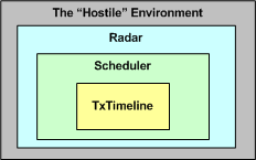
When fully developed and tested, the radar will be fielded within a hostile environment where it will (hopefully) perform its noble mission of detecting and tracking aircraft in the midst of random noise, unwanted clutter reflections, cleverly uncooperative “enemy” pilots, and atmospheric attenuation/distortion. But I digress, so let me get back to the original intent of this post, which I think has something to do with how and why I use the UML.
The radar transmit timeline is where other necessarily closely coupled scheduler sub-components add/insert commands that tell the radar hardware what to do and when to do it; sometime in the future relative to “now“. As the radar rotates and fires its sophisticated, radio frequency pulse trains out into the ether looking for targets, the scheduler is always “thinking” a few steps ahead of where the antenna beam is currently pointing. The scheduler relentlessly fills the TxTimeline in real time with beam-specific commands. It issues those commands to the hardware early enough for the hardware to be able to queue, setup, and execute the minute transmit details when the antenna arrives at the desired command point. Geeze! I’m digressing yet again off the UML path, so lemme try once more to get back to what I originally wanted to ramble about.
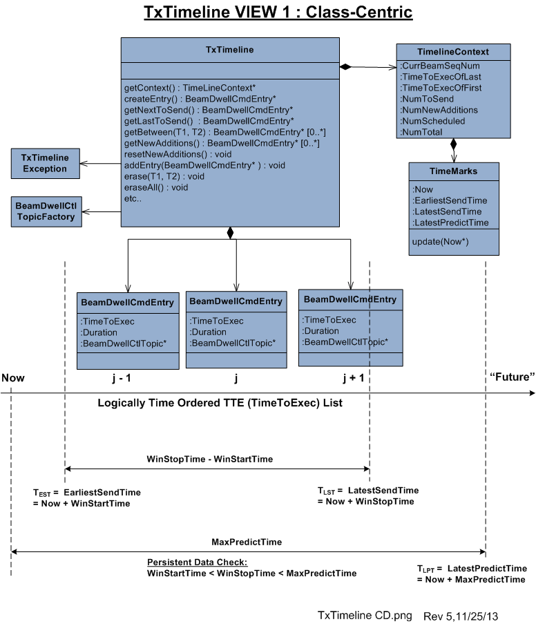
Being an unapologetic UML bender, and not a fan of analysis-paralysis, I never attempt to meticulously show every class attribute, operation, or association on a design diagram. I weave in non-UML symbology as I see fit and I show only those elements I deem important for creating a shared understanding between myself and other interested parties. After all, some low level attributes/operations/classes/associations will “go away” as my learning unfolds and others will “emerge” during coding anyway, so why waste the time?
Notice the “revision number” in the lower right hand corner of the above class diagram. It hints that I continuously keep the diagram in sync with the code as I write it. In fact, I keep the applicable diagram(s) open right next to my code editor as I hack away. As a PAYGO practitioner, I bounce back and forth between code & UML artifacts whenever I want to.
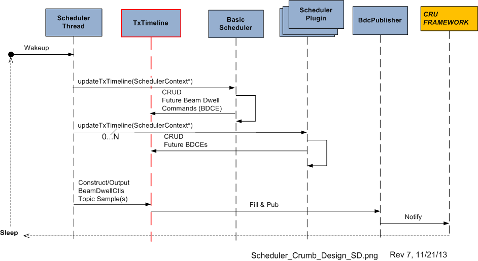
The UML sequence diagram below depicts a visualization of the participatory role of the TxTimeline object in a larger system context comprised of other peer objects within the scheduler. For fear of unethically disclosing intellectual property, I’m not gonna walk through a textual explanation of the operational behavior of the scheduler component as “a whole“. The purpose of presenting the sequence diagram is simply to show you a real case example that “one diagram is not enough” for me to capture the design of any software component containing a substantial amount of “essential complexity“. As a matter of fact, at this current moment in time, I have generated a set of 7+ leveled and balanced class/sequence/activity diagrams to steer my coding effort. I always start coding/testing with class skeletons and I iteratively add muscles/tendons/ligaments/organs to the Frankensteinian beast over time.
In this post, I opened up my trench coat and showed you my… attempted to share with you an intimate glimpse into the way I personally design & develop software. In my process, the design is not done “all upfront“, but a purely subjective mix of mostly high and low level details is indeed created upfront. I think of it as “Big Design, But Not All Upfront“.
Despite what some code-centric, design-agnostic, software development processes advocate, in my mind, it’s not just about the code. The code is simply the lowest level, most concrete, model of the solution. The practices of design generation/capture and code slinging/testing in my world are intimately and inextricably coupled. I’m not smart enough to go directly to code from a user story, a one-liner work backlog entry, a whiteboard doodle, or a set of casual, undocumented, face-to-face conversations. In my domain, real-time surveillance radar systems, expressing and capturing a fair amount of formal detail is (rightly) required up front. So, screw you to any and all NoUML, no-documentation, jihadists who happen to stumble upon this post. 🙂
Working Code Over Comprehensive Documentation
Comprehensiveness is the enemy of comprehensibility – Martin Fowler
Martin’s quote may be the main reason why this preference was written into the Agile Manifesto…
Working software over comprehensive documentation
Obviously, it doesn’t say “Working software and no documentation“. I’d bet my house that Martin and his fellow colleagues who conjured up the manifesto intentionally stuck the word “comprehensive” in there for a reason. And the reason is that “good” documentation reduces costs in both the short and long runs. In addition, check out what the Grade-ster has to say:
The code tells the story, but not the whole story – Grady Booch
Now that the context for this post has been set, I’d like to put in a plug for Simon Brown’s terrific work on the subject of lightweight software architecture documentation. In tribute to Simon, I decided to hoist a few of his slides that resonate with me.


Note that the last graphic is my (and perhaps Simon’s?) way of promoting standardized UML-sketching for recording and communicating software architectures. Of course, if you don’t record and communicate your software architectures, then reading this post was a waste of your time; and I’m sorry for that.

Annoying And Disappointing
Atego’s Artisan Real-Time Studio, Sparx’s Enterprise Architect, and IBM’s Rational Rhapsody are big and expensive UML modeling tools. You would think they support all of the basic visual modeling elements of the UML, no?
On the left side of the figure below, I show the four fundamental, visual UML symbols for conjuring up (wrong, incomplete, and inconsistent) structural views of an object-oriented software system in the form of class diagrams, deployment diagrams, component diagrams, etc.

It blows BD00’s already incoherently twisted mind that Artisan Studio doesn’t provide visual elements for a UML Node or a Component. As can be seen on the right side of the figure, the work-around is to use stereotyped Classifier elements to fill the void. It’s annoying and disappointing, dontcha think?
But hey, not many people (especially extreme left-wing agile zealots) buy into the potential of the UML for shortening the development time and long-term cost of big, sprawling, long-lived software systems . So, “meh” to this irrelevant post.
Note: I’m a relatively newbie user of Artisan Studio. If you’re an advanced user and you know that I’m mistaken here, then please speak up and tell me how to find these two seemingly-hidden buggers.
Irritated
Unsurprisingly, one of BD00’s posts irritated a reader who stumbled upon it. For some strange reason, BD00’s scribblings have that effect on some people. In the irritating post, “The Old Is New Again“, BD00 referred to Data and Control Flow diagrams as “old and obsolete“. In caustic BD00 fashion, the reader commented:
Use Cases and Activity Diagrams, in contrast (to the Data Flow diagram), offer little guidance in effective partitioning. They rely upon the age old “sledge hammer” approach to partitioning” (ie, just break-er-up any way you can). Sledge hammer partitioning is what cave men used to partition entities. So in a critical sense, DFD’s are new and hip, while Use Cases and Activity Diagrams are based upon logic that is older than dirt.
BD00 likes all visual modeling tools – including the DFD hatched during the heyday of structured analysis. BD00 only meant “old and obsolete” in the sense that DFDs pre-dated the arrival of the UML and the object-oriented approach to system analysis and design. However, BD00 did feel the need to correct the reader’s misunderstanding of the features and capabilities that UML Activity Diagrams offer up to analysts/designers.
Both the DFD and UML activity diagram pair below equivalently capture an analyst’s partitioning design decision (where DFD Process X == Activity Diagram Action X). Via “swimlanes“, the lower activity diagram makes the result of a second design decision visible: the conscious allocation of the Actions to the higher level Objects that will perform them during system operation. So, how are UML activity diagrams inferior to DFDs in supporting partitioning? A rich palette of other symbols (forks, joins, decisions, merges, control flows, signals) are also available to analysts (if needed) for capturing design decisions and exposing them for scrutiny.

DFDs and UML diagrams are just tools – job performance aids. Learning how to use them, and learning how to use them effectively, are two separate challenges. Design “guidance” for system partitioning, leveling, balancing, etc, has to come from somewhere else. From a mentor? From personal experience learning how to design systems over time? From divine intervention?
Broken, Not Bent
It’s one thing to “bend” the UML to express a design concept that you don’t know how to express with the language, but it’s another thing to “break” it outright. By “break“, I mean drawing old-school, ad-hoc, single-symbol diagrams that all look alike and passing them off as UML class, deployment, activity, etc, diagrams.
By propagating broken UML diagrams out into the world in a sincere, but fruitless, attempt to establish a shared understanding among team members, the exact opposite can occur – mass confusion and an error prone, friction-filled development effort. Even worse, presenting the ad-hoc quagmire to customers and financiers who have a rudimentary education in object orientation and UML can cause them to question the competence of the presenters and the wisdom of their investment choice.
But hey, there’s nothing to worry about. Nobody understands or cares about the UML anyway. Thus, the ambiguity, inconsistency, and conflicts inherent in the design won’t be exposed (or ever traced-back-to) if schedule and cost disaster strikes.

All models are wrong. Some, however, are useful. – George E. Box
Related articles
- Proprietary Extensions (bulldozer00.com)
- UML Tool for Fast UML Diagrams (allincircles.wordpress.com)
- Mind Maps: The Poor Man’s Design Tool (drdobbs.com)
Proprietary Extensions
When using a tool or technology that implements a universal standard, beware of inadvertently using non-standard extensions that “lock” you into the vendor’s revenue stream.
The graphic below shows a screenshot from Artisan Real-time Studio version 7.2. Even though the tool implements the UML 2.0 standard, notice that there are several “non-UML” diagrams that you can create: “Constraint Diagram“, “General Flow Diagram“, etc. If you choose to create and use these proprietary extensions, then you’re sh*t out of luck if you get pissed off at Atego and want to port your model over to a different UML tool vendor with a better and/or less expensive solution. D’oh! I hate when that happens.

I’m not trying to single out Atego here. Every commercial vendor, especially of expensive tools, bakes-in a few proprietary extensions to give them an edge over the competition. The sneakier ones don’t annotate or make obvious which features are proprietary – so beware.
Monopolistic Providers
In search of economies of scale, centrally planned and controlled economies in nations and corporations tend to create monopolistic providers of goods and services. For example, in corporations, accounting, personnel, and R&D departments are usually deliberately organized as subsidized monopolies. They are subsidized in the sense that the users of their products or services do not pay for them directly; the supplying units are supported financially by funds that are allocated to them from above. The pool from which these funds are drawn is filled by a “tax” allocated from above to the units served. Monopolistic units that are subsidized are generally insensitive and unresponsive to the users of their services, but they are sensitive and responsive to the desires of the higher-level units that subsidize them. These higher level units are even more removed from the units served than the serving units. As a result, they are often unaware of, or unresponsive to, the needs and desires of the internal users of monopolistically provided goods and services. – Russell Ackoff (Ackoff’s Best: His Classic Writings on Management)
OK, time to practice my “bent” UML modeling skills and test your understanding with the class and sequence diagram pair below. The class diagram provides a structural view of a fictional Ackoffian system. The sequence diagram steps through an amalgam of behaviors in a world where monopolies rule. Any questions, comments, critiques, accolades, WTFs?


The Scrum Sprint Planning Meeting
Since the UML Scrum Cheat Sheet post is getting quite a few page views, I decided to conjure up a class diagram that shows the static structure of the Scrum Sprint Planning Meeting (SPM).
The figure below shows some text from the official Scrum Guide. It’s followed by a “bent” UML class diagram that transforms the text into a glorious visual model of the SPM players and their responsibilities.

In unsuccessful Scrum adoptions where a hierarchical command & control mindset is firmly entrenched, I’ll bet that the meeting is a CF (Cluster-f*ck) where nobody fulfills their responsibilities and the alpha dudes dominate the “collaborative” decision making process. Maybe that’s why Ramblin’ Scott Ambler recently tweeted:
Everybody is doing agile these days. Even those that aren’t. – Scott Ambler
D’oh! and WTF! – BD00
Of course, BD00 has no clue what shenanigans take place during unsuccessful agile adoptions. In the interest of keeping those consulting and certification fees rolling in, nobody talks much about those. As Chris Argyris likes to say, they’re “undiscussable“. So, Shhhhhhh!
Scrum Cheat Sheet
While reading Schwaber and Sutherland’s official Scrum Guide, I decided to concoct a graphical UML-heavy cheat sheet of the monstrously famous agile framework.
Scrum Framework Components

System Class Diagram

Scrum Roles

Scrum Events

Scrum Artifacts

Who am I?
Why am I here?
WTF?
Meh!
D'oh!
My BTC Address